Overview
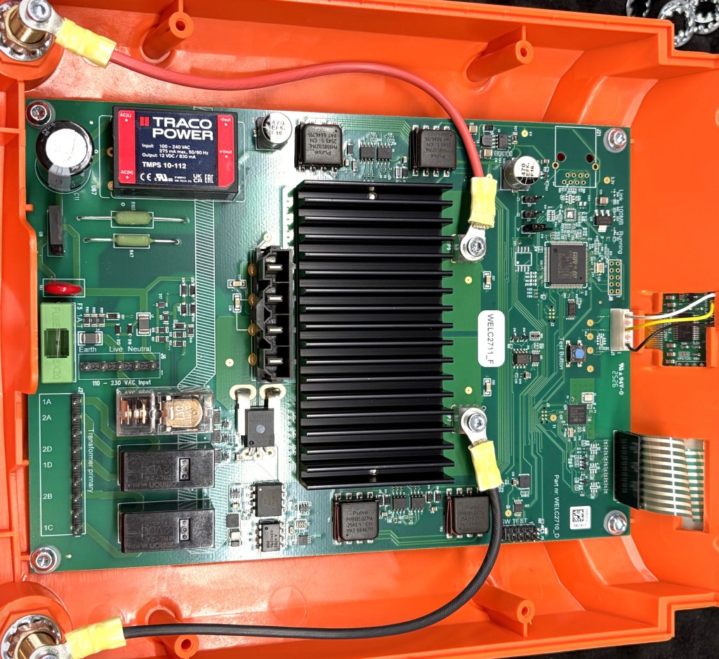
A client was developing three industrial power electronics boards that were designed to support two alternative AC-DC power modules through a shared dual footprint:
- TRACO Power TMPS 10 Series
- MEAN WELL IRM-10 Series
The objective of the dual footprint was to provide sourcing flexibility by allowing either power module to be assembled on the same PCB design depending on component availability.
The boards successfully passed schematic review, PCB layout review, Gerber verification, and manufacturing preparation. The Gerber files were reviewed by the circuit engineer and additional external consultants before being released for production.
The Challenge
After PCB fabrication was completed and assembly began, the contract manufacturer reported an unexpected issue.
The TRACO module could be assembled successfully, but the MEAN WELL module could not be mounted on the PCB footprint.
The assembly house attempted installation from both the top side and bottom side of the board but found that the pin arrangement did not match the PCB footprint in either orientation.
According to the pick-and-place data and assembly documentation, the component was intended to be mounted on the top side of the PCB. However, physical verification showed that the footprint did not properly support the MEAN WELL module.
At this stage, fabricated PCBs had already been produced, creating a potential risk of scrapping inventory and delaying production schedules.
Investigation
I was asked by the client to investigate the issue and determine the root cause.
The following items were reviewed:
- Original schematic library
- PCB footprint library
- Component datasheets
- Assembly documentation
- Pick-and-place files
- Fabricated PCB data
A detailed comparison was performed between the dual footprint implementation and the manufacturer datasheets for both power modules.
Root Cause
The investigation revealed that the dual footprint had been created using the wrong reference orientation.
Instead of using the component’s top-view pin orientation from the datasheets, part of the footprint had been created using a bottom-view interpretation.
Because of this orientation error:
- The TRACO module remained compatible with the footprint.
- The MEAN WELL module’s pin locations became mirrored relative to the PCB pads.
- The module could not be physically installed from either side of the PCB.
This issue was not detected during design review because the footprint geometry appeared visually correct within the CAD environment. The discrepancy only became apparent when physical components were introduced during assembly.
Immediate Corrective Action
Since fabricated boards were already available, the primary objective was to avoid scrapping inventory.
The client confirmed that the previous production runs used only the TRACO module.
Therefore, the immediate corrective action was:
- Continue assembling the completed PCB inventory using the TRACO module.
- Avoid reworking or discarding fabricated boards.
- Maintain production continuity while a permanent solution was developed.
This approach allowed the client to utilize existing PCB inventory and avoid manufacturing losses.
Permanent Design Fix
A complete review and redesign of the dual footprint was performed.
The updated footprint was recreated using the correct top-view reference orientation from both manufacturers’ datasheets.
The redesign included:
- Verification of all pin locations
- Verification of pin numbering
- Mechanical fit checks
- Footprint overlap validation
- Assembly orientation validation
- Manufacturing output verification
After implementing the corrections:
- New PCB design files were generated.
- Updated Gerber files were produced.
- Updated manufacturing outputs were released for all three boards.
The corrected footprint now supports both:
- TRACO TMPS 10 Series
- MEAN WELL IRM-10 Series
without assembly conflicts.
Engineering Lessons Learned
This project reinforced several important PCB library-development principles:
1. Always Verify Datasheet View Orientation
Many through-hole and power-module datasheets present mechanical drawings in different viewing orientations.
A footprint should always be validated against the manufacturer’s specified PCB mounting view before release.
2. Dual Footprints Require Physical Validation
Even when electrical connectivity appears correct, mechanical compatibility must be independently verified for every supported component.
3. Library Reviews Should Include Mechanical Checks
Schematic reviews, ERC checks, DRC checks, and Gerber reviews alone may not detect footprint orientation errors.
Mechanical verification against actual component geometry is equally important.
4. Production Feedback Is Valuable
The issue was identified quickly because the assembly house performed a physical fit verification before volume assembly began.
Strong communication between design and manufacturing teams helped prevent larger production impacts.
Outcome
The issue was successfully identified and resolved before deployment.
Results achieved:
- Root cause identified during assembly stage.
- Existing PCB inventory preserved.
- Production delays minimized.
- Corrected dual footprint released for future builds.
- Three board designs updated with revised manufacturing files.
- Future compatibility ensured for both approved power modules.
Key Skills Demonstrated
- PCB Library Development
- Footprint Verification
- Manufacturing Support
- Design-for-Assembly (DFA)
- Root Cause Analysis
- Corrective and Preventive Action (CAPA)
- Gerber Release Management
- Power Electronics PCB Design
- Multi-Vendor Component Integration
Client name, product name, board names, production quantities, and proprietary design information have been intentionally omitted to protect confidentiality.


Leave a Reply